
Control Arm Bushing Replacement DIY Guide
DISCLAIMER
As always, follow all safety protocols. Don't undertake this task if you aren't comfortable with it, fully understand it, and are capable of completing it. The information provided may be incomplete or inaccurate. You are ultimately responsible for anything you do. Neither Redpants, LLC or myself is responsible or liable for anything that may occur.
WARNING
This is not a simple job and isn’t one I’d recommend unless you have experience doing this sort of work. Not only does the job take certain, specific tools and a lot of time, it can also result in damage to suspension components during the job or an incident while driving afterwards. I highly recommend leaving this job to a shop that has the tools and experience required for this job.
I’m going to say right up front that this isn’t a quick or easy job and it’ll be infinitely more difficult without the right tools. It also involves a couple, um, “procedures” that might not be for the feint of heart. I went through this job on my grey 2007 V8 Vantage to replace the OEM bushings with a Powerflex’s polyurethane control arm bushings and sway bar bushings.
Needed
New bushings
- DBS / V8V / V12V / Virage
- DB9.1
15mm, 18mm, and 21mm long-handle wrenches
10mm, 15mm, 18mm, and 21mm sockets
Ratchets for the above sockets
Fir tree removal tool
Ball joint splitter
Air/power tools
20-Ton press
Ball joint removal tools
Flat and curved files
Mallet (recommended)
Prybar (recommended)
2-3 hours per corner
Torque Ratings
Front lower control arm forward bolt to subframe: 185 Nm. (137 lb/ft)
Front lower control arm rearward bolt to subframe: 115 Nm. (85 lb/ft)
Front lower control arm to upright assembly: 90 Nm. (66.5 lb/ft)
Front upper control arm bolts to chassis: 115 Nm. (85 lb/ft)
Front upper control arm to upright assembly: 90 Nm. (66.5 lb/ft)
Rear lower control arm bolt to subframe: 115 Nm. (85 lb/ft)
Rear upper control arm bolts to subframe: 115 Nm. (85 lb/ft)
Coilover top nuts: 22.5 Nm. (17 lb/ft)
Coilover bottom bolt: 175 Nm. (129.5 lb/ft)
Sway bar end links: 110 Nm. (81.5 lb/ft)
Before You Begin
While this can be done as a one-person job, it’s much easier if you have a second person to help out.
The upright assembly is also commonly called a knuckle, knuckle joint, and Aston Martin refers to it as a vertical link. I’ll be referring to it throughout this DIY Guide as an upright assembly.
If you’re replacing your coilovers at the same time as your control arm bushings, I found certain orders worked best.
Front order
Lower control arm out
Coilover out
Lower control arm in
Upper control arm out
Coilover in
Upper control arm in
Rear order
Lower control arm outer bolts out
Coilover out
Lower control arm reconnected
Upper control arm out
Upper control arm in
Coilover in
Lower control arm out
Lower control arm in
Removing the ball joint from a control arm can be very difficult to do, even with the correct tool. Don’t be surprised if you need to use a mallet to finesse the bejesus out of the ball joint to get it loose. If you do go the mallet route, it helps to put the nut back onto the ball joint stud and thread it enough that the top of the nut and the end of the stud are flush - this will give a better surface for the mallet to hit and also protect the threads of the stud.
Removing a bushing from a control arm can be very difficult to do, even with the correct tool. Be very careful to not damage the control arm. Once a bushing is removed, the control arm should be cleaned of any corrosion, burs, shavings, or anything else before the new bushing is installed.
Do not forget the headlight leveling sensors that are connected to the lower control arms. Failure to disconnect these before removing the lower control arms can damage the sensors, and not connecting the sensors when reinstalling the lower control arms can cause your headlights to aim improperly. There is one sensor connected to the front left lower control arm and one sensor connected to the rear left upper control arm.
I highly recommend getting an alignment after changing the suspension bushings. Not getting an alignment can cause poor or unpredictable vehicle handling, uneven tire wear, and other issues.
Notes About Powerflex Bushings
Powerflex bushings include their own lubricant. The rule of thumb is that the polyurethane bushings should be lubricated on any surface that touches anything else (washers, dowels, etc).
The suspension should be preloaded when tightening the various control arm bolts to install rubber bushings. Not doing this can cause them to bind and tear, leading to premature bushing failure. Powerflex’s polyurethane bushings do not require preloading of the suspension, so the bolts can be tightened during the course of installation while the car is still off the ground.
Step 1
Break the lug nuts loose on each wheel, then get the car on jack stands or use a lift.
Remove all four wheels and all four fender liners.
Step 2
Disconnect the front sway bar from the end links on both sides. A set of thin vice grips can make this much easier.

Step 3
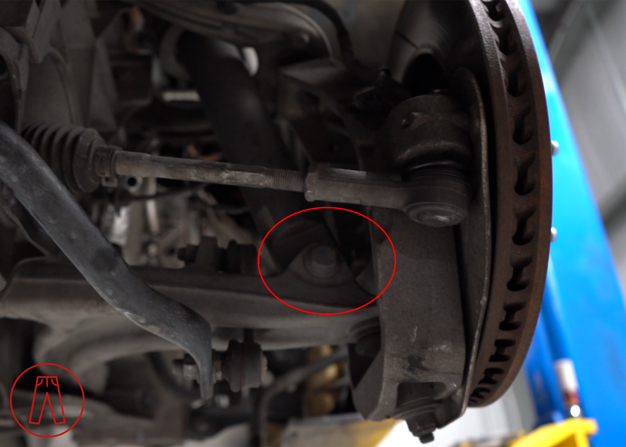
If present, unbolt the level sensor arm from the lower control arm.

Remove the ball joint nut at the outer edge of the front lower control arm connecting it to the knuckle, then separate the ball joint from the lower control arm.

Remove the bolt that secures the bottom of the coilover to the lower control arm.
Remove the two bolts that secure the lower control arm to the front subframe.

Remove the lower control arm from the vehicle.
Step 4
If you’re replacing the coilovers as part of this job, remove the coilover.
Remove the old bushings and replace them with the new ones.
Reinstall the lower control arm using Step 3’s instructions, but in reverse.
Step 5
Pop the fir tree clips loose from the upper control arm.

Remove the ball joint nut at the outer edge of the upper control arm connecting it to the knuckle, then separate the ball joint from the upper control arm.

Remove the two bolts that attach the upper control arm to the chassis.
Step 6
Remove the old bushings and replace them with the new ones.
If you’re replacing the coilovers as part of this job, install the coilover.
Reinstall the upper control arm using Step 6’s instructions, but in reverse.
Step 7
Repeat Steps 3 through 6 for the other side.
Step 8
Reconnect the front sway bar to the end links on each side.
Reinstall the engine strut brace if removed to replace the coilovers.
Step 9
Disconnect the rear sway bar from the end links on both sides.
Step 10
Remove the bolt that connects the headlight level sensor arm to the rear upper control arm, then push the level sensor arm back toward the sensor to keep it out of the way.

Step 11
Remove the bolt that secures the outer end of the rear lower control arm to the upright assembly (knuckle) and the bolt at the bottom of the coilover to the rear lower control arm.

Loosen the bolts that hold the rear lower control arm to the rear subframe but don’t remove them. Loosening them will make it easy to push the rear lower control arm down to give clearance for the coilover to be removed in the next step.

Note: The rearward bolt attaching the lower control arm to the rear subframe has a bolt and nut, but the forward bolt is just the bolt and does not have a separate nut. Rather, the “nut” is fixed to the subframe (pictured below).

Step 12
Remove the rear coilover, then lift the lower rear control arm back up and insert the outer bolt to reconnect it to the upright assembly (knuckle). This will help control the weight and movement of the upright assembly.
Use a strap, bungie cord, or hanger to hold the weight of the upright assembly to prevent the brake line from being stretched or strained.
Step 13
Remove the outer bolt from the upper control arm that attaches it to the upright assembly, then use a hanger, strap, or similar to support the weight of the upright assembly so it doesn’t drop down and strain the brake line.

Remove the two bolts that hold the rear upper control arm to the rear subframe. The upper control arm can now be removed from the car.

Step 14
Replace the bushings on the upper control arm, then reinstall it. If you’re using Powerflex bushings, take special note of the dowels and washers:
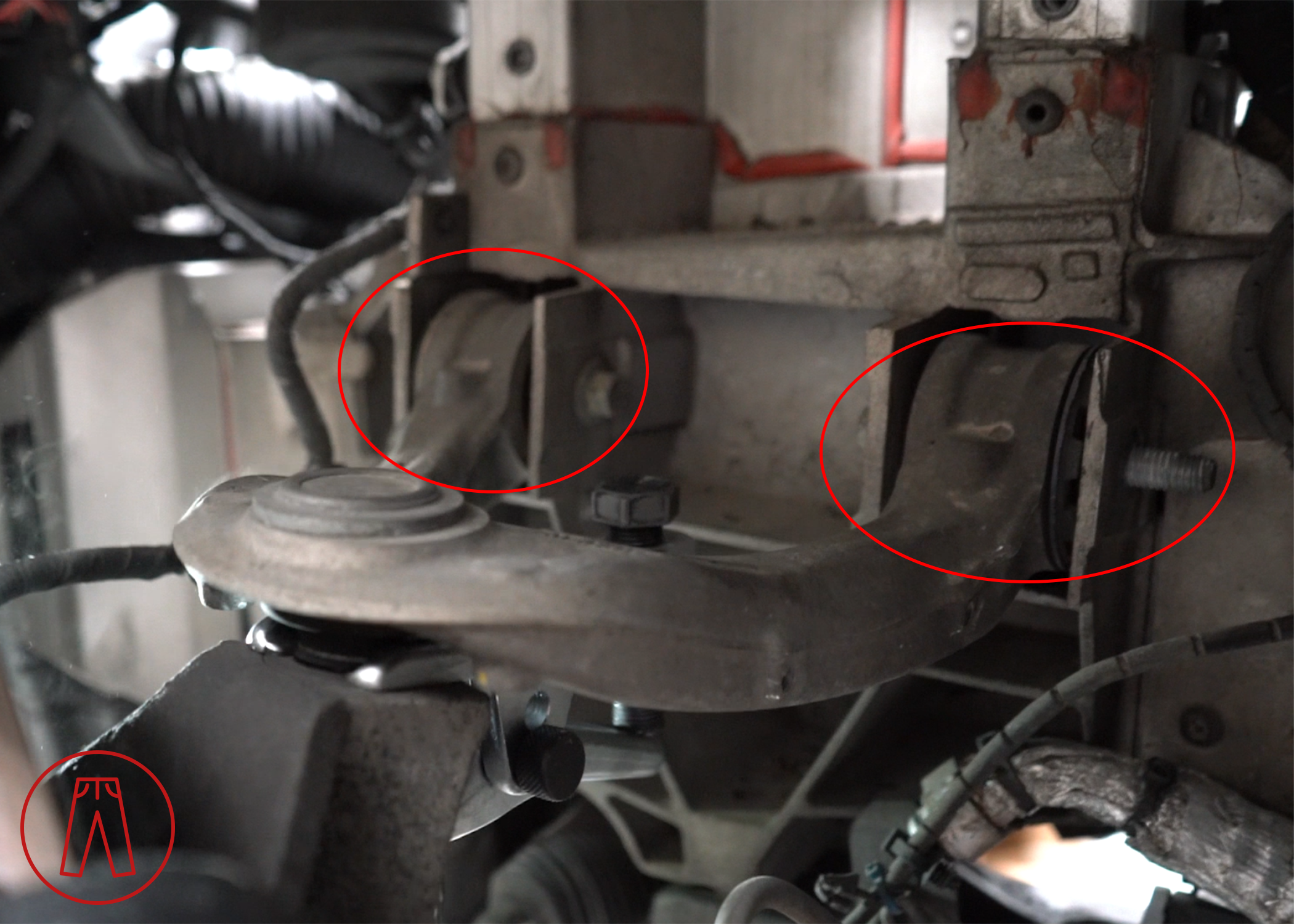
There are four dowels in the package (two for each rear upper control arm). The shorter dowel goes in the front bushing of the rear upper control arm, the longer dowel goes into the rear bushing. The shorter dowel should be fit flush to the bushing on the rear side of the front bushing, which you can see me pointing at in the picture below, and noting the bushing in the rear dowel is not flush to the bushing.

There are six nylon washers and two steel washers in the package (3 nylon washers and one steel washer for each side). The hole size in the steel washer is the same as that of the bolt hole in the dowel, while the holes in the nylon washers are the size of the dowels themselves.

The steel washer is used against the bushing where the shorter dowel is flush with the bushing. Notice its position below.

Step 15
Remove the outer bolt that connects the rear lower control arm to the upright assembly, and then the two bolts holding the rear lower control arm to the chassis.
Step 16
Reinstall the upper portion of the coilover (but not the bolt at the bottom of the coilover).
Step 17
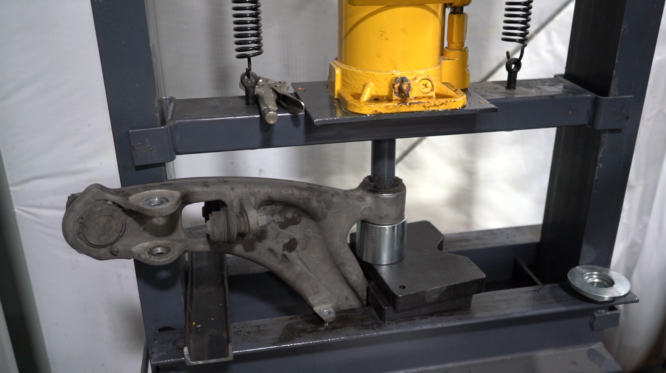
Remove the bushings from the rear lower control arm. The best way I found to do this was to first “break the core out” by using the ball joint removal tool and then using the press.
Warning: Do NOT use a press alone to push the bushings out of the rear lower control arm unless you can completely isolate each bushing as this can bend the control arm.
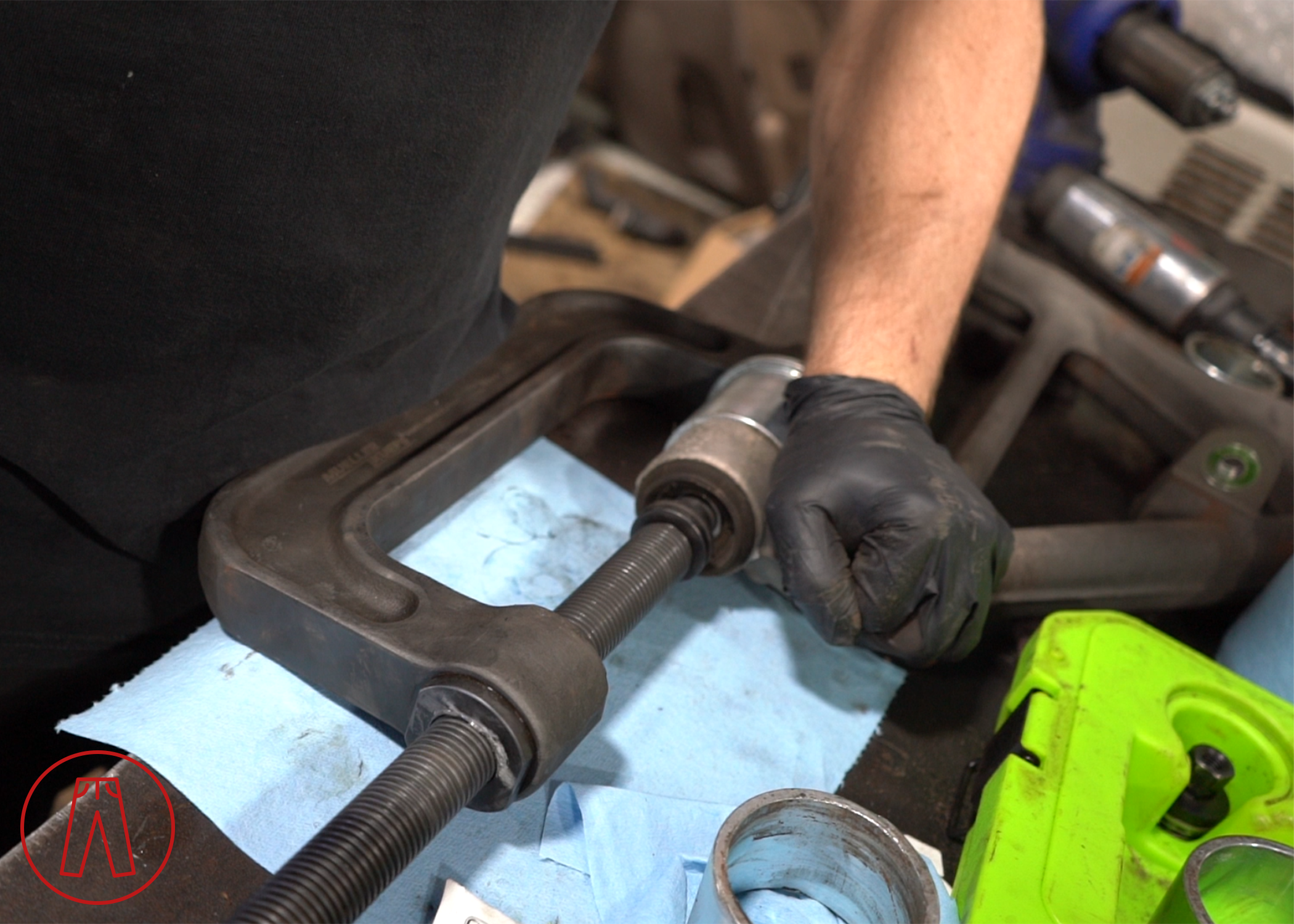
The picture below shows half the bushing being pressed out after the core was broken loose using the vice as shown in the picture above.

Install the new bushings and reinstall the rear lower control arm.
Step 18
Repeat Steps 11 through 17 for the other side.
Step 19
Reconnect the headlight level sensor arm that was unbolted in Step 10.
Reconnect the rear sway bar to the end links on each side.
Step 20
Make sure all the fasteners are properly attached and torqued, then reinstall the fender liners and wheels.
Check to make sure none of the bushings are binding or creaking, there are no knocking sounds in the suspension, or any other issues.
Get a full alignment.
And that’s it!